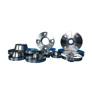
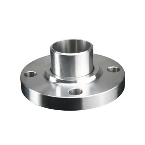
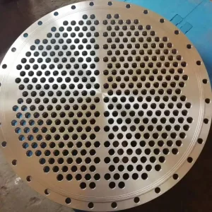
Explore high-precision forged flanges manufactured in compliance with ASME B16.5, ASME B16.47, DIN, and EN 1092-1 international piping codes.
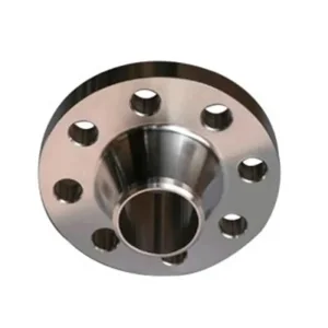
Analyzing modern piping architecture, pressure containment dynamics, and space-constrained hydraulic system requirements.
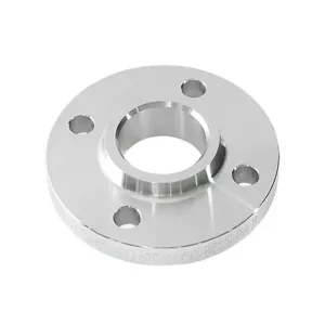
In the contemporary landscape of heavy process industries—spanning offshore oil & gas production, petrochemical refining, nuclear power auxiliary systems, and high-pressure chemical manufacturing—the demand for reliable, leak-free fluid routing is paramount. Among specialized piping components, the Reducing Socket Weld (SW) Flange occupies a critical niche. Designed to connect pipes of different nominal diameters without requiring a separate concentric or eccentric pipe reducer, this component combines diameter transition and flanged joint disconnect capabilities into a single forged monolithic block.
From a commercial and EPC (Engineering, Procurement, and Construction) standpoint, eliminating intermediate butt-weld joints yields substantial capital expenditure (CAPEX) and operational expenditure (OPEX) savings. A traditional line reduction utilizing a standard socket weld flange welded to a concentric swage nipple or pipe reducer requires two circumferential welds, doubled Non-Destructive Testing (NDT) cycles, and extended fit-up labor. By contrast, integrating a socket weld reducing flange cuts installation time by over 45%, reduces total system footprint, and removes one potential leak path from high-pressure lines carrying volatile or toxic media.
Precision-machined internal transitions prevent boundary layer turbulence, minimizing pressure drops across small-to-medium bore line contractions.
Forged grain flow follows the flange contour, offering superior resistance to cyclic fatigue, thermal shock, and line vibration compared to cast alternatives.
Reduces field welding, inspection overheads, and inventory SKU counts by merging connection and reduction features into a single unit.
Understanding ASME B16.5, ASME B16.11, MSS SP-83, and critical expansion gap rules for socket weld assemblies.
A non-negotiable engineering rule for installing socket weld reducing flanges—dictated by ASME Section VIII and ASME B31.3 Process Piping Codes—is the provision of a 1.6 mm (1/16 in) expansion clearance between the pipe end and the bottom of the flange socket prior to fillet welding. Failure to maintain this gap results in severe thermal expansion stress during fluid heating cycles, causing high localized stresses at the root of the fillet weld that lead to stress corrosion cracking (SCC) or low-cycle fatigue failure.
| Piping Connection Method | Weld Count per Reduction | NDT / Radiography Burden | Vibration & Fatigue Resistance | Installation Labor Time |
|---|---|---|---|---|
| Reducing Socket Weld Flange | 1 Fillet Weld | Low (Surface PT/MT) | Very High (Forged Monolithic) | Baseline (Fastest) |
| Standard Socket Weld Flange + Swage Nipple | 2 Fillet Welds | Medium (2x PT/MT) | Moderate (Multiple Joints) | +85% Time Increase |
| Weld Neck Flange + Concentric Reducer | 2 Butt Welds | High (Full RT / UT) | High (Smooth Transition) | +140% Time Increase |
| Threaded Reducer Flange | 0 Welds (Threaded) | Visual Only | Low (Crevice Corrosion Risk) | Fast (Low Pressure Only) |
Selecting the proper forging material grade determines the longevity of the reducing socket weld flange under extreme mechanical loads and corrosive chemical exposure:
Cross-sector deployments of reducing socket weld flanges in high-stakes processing plants.
Used extensively in modular chemical injection skids where space is constrained. The socket weld design allows fast alignment of small-bore dosing lines (1/2" to 2" NPT/SW) into larger manifold headers (3" to 6").
Auxiliary boiler feed lines and steam sampling taps experience significant thermal cycling. Forged ASTM A105 or A182 F11 socket weld reducing flanges isolate vibration and maintain tight seal integrity under ASME Class 600 to Class 1500 pressures.
FPSO (Floating Production Storage and Offloading) vessels require compact component design. Stainless steel and Duplex reducing socket weld flanges minimize structural weight while withstanding harsh salt-spray environments.
How modern forging technology, automated machining, and NDT inspection redefine flange reliability.
Unlike open-die hammering, advanced hydraulic closed-die forging ensures uniform grain flow lines along the flange hub and socket bore. This grain refinement maximizes yield strength and impact energy absorption, critical for severe duty applications.
Computer-controlled turning and drilling guarantee tight tolerances on socket depth, counterbore diameter, flange thickness, and facing finish (125-250 µin AARH stock finish or smooth finish per specification).
Every single flange is hard-stamped with a unique Heat Code linking directly to EN 10204 3.1 / 3.2 Mill Test Certificates (MTC). Chemical analysis (spectrometry) and mechanical properties (tensile, yield, impact) are digitally archived for 30+ years.
Integrating Phased Array Ultrasonic Testing (PAUT) and Magnetic Particle Inspection (MPI) guarantees zero internal voiding, inclusions, or surface micro-fissures in high-pressure socket weld reducing components.
Key parameters for evaluating flange manufacturers to ensure total compliance and risk mitigation.
When selecting a supplier or factory for Reducing Flange Socket Weld components, global procurement officers and piping engineers must verify the manufacturer's credentials against stringent international quality benchmarks:
Direct answers from senior metallurgists and piping application engineers.
Explore custom OEM components, lap joint flanges, tube sheets, and specialty reducer flanges.